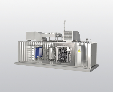
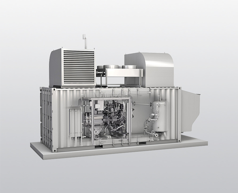
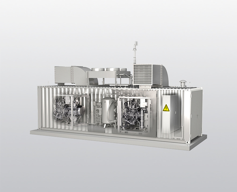
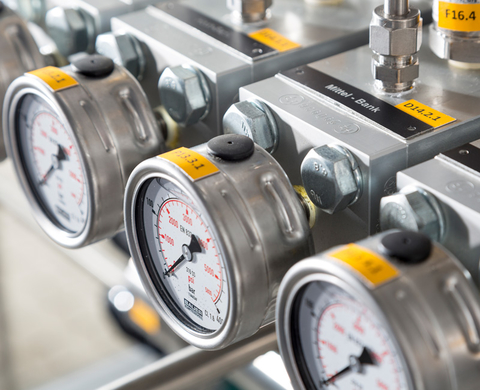
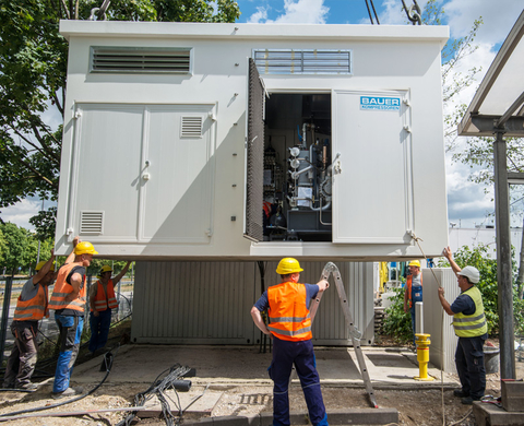
The CS 23 – CS 52 series in two space-saving designs with high daily capacity: For busy public filling stations and any application
High daily capacity: For more than 200 passenger cars/day or 20 HGV/day
The very latest technology and safety: In the very best BAUER quality
Spatially optimised for wherever space is at a premium: Compact, modular design and powerful with housing made from concrete or steel for sound insulation and weather protection
Global spare parts guarantee over 25 years: Your investment could not enjoy better protection
On-site installation and commissioning by experts: Our experienced specialists and engineers will attend your site to carry out this work
The basic version of the CS 23 – CS 52 is designed for operation with one compressor and a storage system. It is ideal for busy public filling stations with a high daily capacity of more than 200 passenger cars/day or 20 HGV/day.
If the number of vehicles to be serviced daily increases, a second compressor can easily be added to the station (which is available in two different designs) and – should refuelling peaks rise – a second storage module.
Its technical benefits (drying on the high-pressure side and monitoring of the pressure dew-point) are also undisputed.
Thanks to the quality that is synonymous with the BAUER name, the filling station can be depended upon for reliable operation at all times, even under maximum stress and load. Furthermore, long service life and spare parts availability (25 years) provide your investment with the very best protection.
All the information you need at your fingertips!
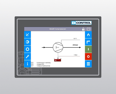
Compressor control
BAUER's B-CONTROL III fully automatic compressor control regulates and monitors all functions of the natural gas filling station from gas input to filling device. Read more
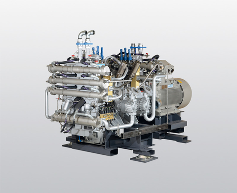
Compressor block
The BAUER compressor blocks have been designed specifically for CNG applications. Exceeding the requirements of all international safety standards, they are characterised by their high energy efficiency and reliability under the most demanding conditions. Read more
High-pressure gas treatment system
The high-pressure gas treatment system (high-pressure filter) is installed downstream of the compressor on the pressure side. Its primary function is to effectively remove excess moisture and possible oil deposits from the natural gas. Read more
Sound insulation and weather protection
The entire unit is integrated inside a housing made from concrete or steel for sound insulation and weather protection.
This provides the best possible protection against the most extreme ambient conditions and, thanks to the use of air handling units or heating systems, can be used in temperature ranges of ±55°C.
Tailored to meet your individual needs, our housings can be fitted with additional important options such as protection against sandstorms.
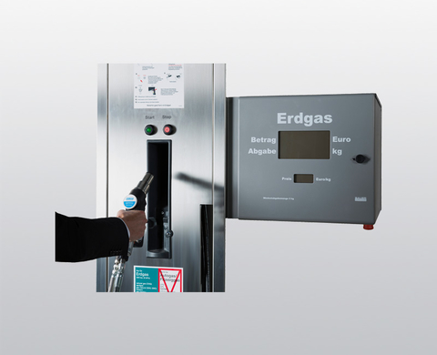
Dispenser/Fill post
This dispensing unit is used for depot refuelling or in public filling stations. Read more
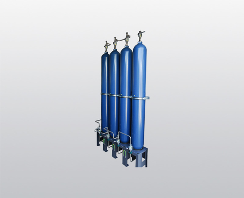
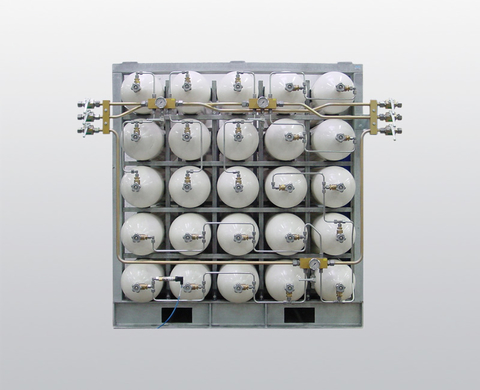
Storage system
The storage systems, which are made up of a number of special high-pressure vessels, are scalable, modular by design and suitable for installation both indoors and outdoors. Read more
Filling and refuelling control
Filling and refuelling control regulates the priority in which the high-pressure storage system is filled. During refuelling, it also regulates the sequence in which gas is withdrawn from the high-pressure storage system. Read more
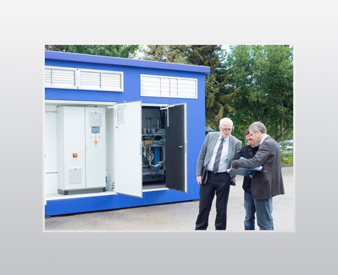
TÜV approval
During technical parts approval testing in the factory prior to delivery, the TÜV carries out comprehensive pressure and safety testing as well as testing the electrical equipment.
Installation/Commissioning
Our regional service teams deliver expert installation and commissioning including comprehensive operator induction. This ensures smooth operation at all times. Read more
Scope of delivery, basic version
Complete compressor unit ready for operation. Read more
| Type designation ³, ⁴ | Inlet Pressure (at first stage compressor) | Capacity ¹ | Working pressure | No. of compr. stages | Standard speed | Motor power | Power consumption ² | ||
|---|---|---|---|---|---|---|---|---|---|
| min. | max. | min. | max. | ||||||
| barg | barg | m³/h | m³/h | barg | rpm | kW | kW | ||
High pressure units | |||||||||
| MFE 120 | 0.05 | 0.3 | 11 | 14 | 300 | 3 | 1340 | 5.5 | 5.2 |
| CTA 15.2-16 | 0.05 | 0.3 | 35 | 43 | 300 | 4 | 1450 | 16 | 14.9 |
| CTA 15.4-16 | 2 | 4 | 30 | 51 | 300 | 3 | 1450 | 16 | 12.3 |
| CTA 22.0-30 | 0.05 | 0.3 | 57 | 72 | 300 | 4 | 1320 | 30 | 27.3 |
| CTA 23.0-37 | 0.05 | 0.3 | 86 | 106 | 300 | 4 | 1200 | 37 | 34 |
| CTA 23.2-37 | 0.05 | 1 | 62 | 118 | 300 | 4 | 1200 | 37 | 35.7 |
| CTA 23.10-37 | 2 | 4.5 | 79 | 146 | 300 | 4 | 1140 | 37 | 35.8 |
| CTA 23.12-37 | 4.5 | 10 | 97 | 195 | 300 | 4 | 1140 | 45 | 40 |
| CTA 23.13-37 | 8 | 14 | 123 | 206 | 300 | 4 | 1140 | 37 | 32.8 |
| CTA 26.0-90 | 0.05 | 0.3 | 193 | 238 | 300 | 4 | 1485 | 90 | 72.7 |
| CTA 26.2-110 | 0.05 | 1 | 161 | 306 | 300 | 4 | 1485 | 110 | 90.5 |
| CTA 26.10-132 | 2 | 4.5 | 307 | 562 | 300 | 4 | 1485 | 132 | 125.2 |
| CTA 26.12-132 | 4.5 | 10 | 317 | 634 | 300 | 4 | 1485 | 132 | 119.2 |
| CTA 26.13-132 | 10 | 16 | 460 | 711 | 300 | 4 | 1485 | 132 | 123.6 |
| CTA 26.14-110 | 16 | 38 | 275 | 654 | 300 | 3 | 1485 | 110 | 86.3 |
| CTA 52.0-160 | 0.05 | 0.3 | 387 | 478 | 300 | 4 | 1485 | 200 | 141 |
| CTA 52.2-200 | 0.05 | 1 | 323 | 613 | 300 | 4 | 1485 | 200 | 181.1 |
| CTA 52.10-315 | 2 | 4.5 | 614 | 1124 | 300 | 4 | 1485 | 315 | 250.4 |
| CTA 52.12-250 | 4.5 | 10 | 634 | 1269 | 300 | 4 | 1485 | 250 | 238.7 |
| CTA 52.13-250 | 10 | 15 | 920 | 1339 | 300 | 4 | 1485 | 250 | 238 |
| CTA 52.14-200 | 16 | 38 | 550 | 1308 | 300 | 3 | 1485 | 200 | 172.7 |
Medium pressure units | |||||||||
| CTA 23.7-37 | 4 | 12 | 117 | 312 | depending on pre-pressure | 2 | 1140 | 37 | 31.8 |
| CTA 23.8-37 | 4 | 10 | 200 | 400 | depending on pre-pressure | 2 | 1140 | 45 | 38 |
| CTA 26.7 | 4 | 10 | 402 | 887 | depending on pre-pressure | 2 | 1485 | 132 | 116 |
¹ Volume flow rate related to 1barg, 0°C gas inlet temperature and 20°C outlet temperature, flow measured at compressor inlet, acc. to ISO1217; tolerance: +/- 5%
² Mechanical power consumption at maximum inlet pressure and discharge pressure of 300 barg resp. 80 and 100 barg
³ CTA 120 , CTA 15.xx & CTA 23.xx are air cooled machines
⁴ CTA 26.xx & CTA 52.xx are water cooled machines


